
|
|
Tài trợ cho PIC Vietnam |
||||||||
| Điều khiển Lý thuyết điều khiển và ứng dụng lý thuyết điều khiển trong những trường hợp thực tế |
 |
|
|
Ðiều Chỉnh | Xếp Bài |
 30-05-2005, 11:07 PM
|
#1 |
|
PIC Bang chủ

Tham gia ngày: May 2005
Bài gửi: 2,631
:   |
Bộ điều khiển fuzzy
Các bạn có thể download chương trình fuzzytech phiên bản 5.52f tại đây và bản crack đi kèm.
Chúc vui.
__________________
Công ty TNHH Thương mại và Giao nhận R&P store.hn@rpc.vn - store.hcm@rpc.vn Học PIC như thế nào? |

|

|
|
02-06-2005, 10:30 PM
|
#2 |
|
Đệ tử 6 túi

Tham gia ngày: Jun 2005
Bài gửi: 141
: |
Không có password thì làm sao cài được chương trình này hả Admin?
|
|
|
|
|
02-06-2005, 10:53 PM
|
#3 |
|
PIC Bang chủ
Tham gia ngày: May 2005
Bài gửi: 2,631
: |
Đó là ý tôi muốn các bạn ít ra cũng phải lên tham quan thử cái trang FuzzyTech xem nó ra làm sao, chứ tôi không muốn các bạn cứ thế là down về xài mà không quan tâm gì đến nó cả.
Trong FuzzyTech nó có hướng dẫn chi tiết làm sao để cài đặt. pw: purple Sau đó các bạn dùng một trong 2 pw này cho phần tiếp theo. pw: 00000 pw: 123456 Chúc vui.
__________________
Công ty TNHH Thương mại và Giao nhận R&P store.hn@rpc.vn - store.hcm@rpc.vn Học PIC như thế nào? thay đổi nội dung bởi: falleaf, 16-11-2005 lúc 08:08 PM. |
|
|
|
|
23-11-2005, 11:22 AM
|
#4 |
|
Nhập môn đệ tử

Tham gia ngày: Nov 2005
Bài gửi: 6
: |
Đây là các bước cài đặt phần mềm fuzzyTech 5.52 từ nguồn của anh admin.Tôi đã cài đặt thành công. Các bạn cứ làm y như thế này là dùng được.
 http://picvietnam.com/download/Fuzzy...YEN.201105.pdf |
|
|
|
|
29-11-2005, 07:20 PM
|
#5 |
|
Nhập môn đệ tử
Tham gia ngày: Nov 2005
Bài gửi: 6
: |
Fuzzy Logic Controller in Matlab7.0
Bài viết sau mô tả quá trình thiết kế và mô phỏng một bộ điều khiển mờ trên Matlab.
Bộ điều khiển mờ ở đây gồm 2 input và 1 output với 3 hàm thuộc cho mỗi input và 5 hàm thuộc cho output. Bộ luật gồm có 5 luật. http://picvietnam.com/download/Fuzzy...YEN.201105.pdf
__________________
Người vá trời lấp bể Kẻ đắp lũy xây thành Ta chỉ là chiếc lá Phận của mình là xanh |
|
|
|
|
17-05-2006, 08:30 PM
|
#6 |
|
Nhập môn đệ tử
Tham gia ngày: May 2006
Bài gửi: 1
: |
Em dang quan tam den viec dua Fuzzy controller len Vi dieu khien ho PIC chang han. Bac nao, co phan mem hay co tai lieu noi ve van de nay, xin vui long post len nhe.
Cam on rat nhieu ncngon |
|
|
|
|
17-05-2006, 09:16 PM
|
#7 |
|
PIC Bang chủ
Tham gia ngày: May 2005
Bài gửi: 2,631
: |
Bạn xem bài toán mẫu viết bằng matlab, từ matlab chuyển sang C hoàn toàn không khác gì nhau. Và chuyển qua vi điều khiển thực chất chỉ là thêm việc xuất các tín hiệu ra port, hoặc đọc các giá trị input từ các port vào thôi.
Chính vì vậy, vấn đề chính là bạn cần tìm hiểu bộ điều khiển fuzzy thật rõ ràng, phần lập trình dùng PIC hoàn toàn không phải vấn đề. Chỉ cần bạn giải một cách rõ ràng bài toán fuzzy trên matlab, mọi thành viên có kinh nghiệm của picvietnam đều có thể giúp bạn lập trình trên PIC một cách rất nhanh chóng. Đừng vội quan tâm tới vi điều khiển ở giai đoạn này, hãy quan tâm đến bài toán fuzzy một cách nghiêm túc. Chúc vui.
__________________
Công ty TNHH Thương mại và Giao nhận R&P store.hn@rpc.vn - store.hcm@rpc.vn Học PIC như thế nào? |
|
|
|
|
15-06-2006, 03:15 PM
|
#8 |
|
PIC Bang chủ
Tham gia ngày: May 2005
Bài gửi: 2,631
: |
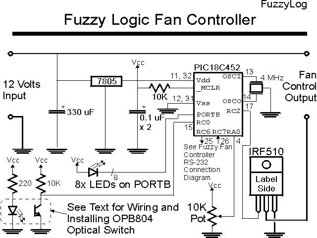
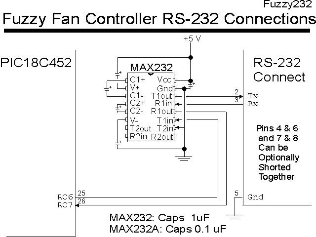
Thực hành một bộ điều khiển fuzzy với PIC
Hãy chuẩn bị những linh kiện sau để bắt đầu
Part Description PIC18C452 PIC18C452-JW 7805 7805 in TO-220 Package MAX232 Maxim MAX232 IRF510 IRF510 N-Channel MOSFET in TO-220 Package OPB804 OPB804 "Slotted Opto Isolator Switch" or equivalent modified as described in the text LED 8x LED, Individual or use 10x LED "Bargraph" Display 4 MHz 4 MHz Ceramic Resonator with Internal Capacitors 10K 2x 10K, 1/4 Watt Resistors 220 220 Ohm, 1/4 Watt Resistor 10K Pot 10K Single Turn Potentiometer 0.1 uF 2x 0.1 uF, 16 Volt Tantalum Capacitors 1.0 uF 5x 1.0 uF, 16 Volt Tantalum Capacitors Miscellaneous Prototyping Card, Wiring, +12 Volt 500 mA Power Supply, 8x Screw Terminal
__________________
Công ty TNHH Thương mại và Giao nhận R&P store.hn@rpc.vn - store.hcm@rpc.vn Học PIC như thế nào? |
|
|
|
|
15-06-2006, 03:17 PM
|
#9 |
|
PIC Bang chủ
Tham gia ngày: May 2005
Bài gửi: 2,631
: |
Sơ đồ nguyên lý
__________________
Công ty TNHH Thương mại và Giao nhận R&P store.hn@rpc.vn - store.hcm@rpc.vn Học PIC như thế nào? |
|
|
|
|
15-06-2006, 03:20 PM
|
#10 |
|
PIC Bang chủ
Tham gia ngày: May 2005
Bài gửi: 2,631
: |
Source code
Phần khai báo
Code:
 title  "fuzzy2 - PIC18C452 Fuzzy Logic Fan Controller"
#define nDebug
;
;  This application uses the "fuzzyTECH" Heater/Motor control Interface
;   to implement a Fuzzy Logic Fan Controller on the PIC18C452.  To simplify the
;   software, the built in functions of the PICmicro to simplify the code development
;   tasks.  This application runs in two modes, a basic POT Interface and a fuzzy logic
;   control interface.
;
;  The Difference between Fuzzy1 and Fuzzy2 is that Fuzzy2 Accepts Deltas to the PWM.
;   This was done to see if the Oscillations can be eliminated.
;
;  Hardware Notes:
;  PIC18C452 running at 4 MHz with "_MCLR" pulled up
;  Clock is running with the 4x PLL Enabled
;  LED Displays:
#define Polling PORTB, 7
#define Sending PORTB, 6
#define Receive PORTB, 5
;  RA2 - Pot Input Pin
#define PotIn   PORTA, 2
;  RC2 - PWM Output Pin
#define PWMOut  PORTC, 2
;
;
  LIST R=DEC, F=INHX32
  INCLUDE "p18c452.inc"


;  Register Usage
 CBLOCK 0x000
TMR1Save:2						;  TMR1 Count Save Value
DDSave, DDOut:4						;  DecDisplay Variables
Dlay:3							;  Delay 1 Second
SetSpeed, DeltaSpeed, LEDTemp				;  Output Values
RXData:16						;  Want to Be able to Delete DPs
NewPWM, TempPWM						;  New PWM Value
 ENDC

;  Macros
TXOut Macro			;  Transmit the Data in "w"
 ifdef Debug
  nop
  nop
 else
  btfss   TXSTA, TRMT		;  Wait for the Previous Byte to be Sent
   bra    $ - (2 * 1)
 endif
  movwf   TXREG			;  Output the Digit
  btg     Sending		;  Indicate Data Being Sent
 endm


 PAGE
 __CONFIG _CONFIG0, _CP_OFF_0
 __CONFIG _CONFIG1, _OSCS_OFF_1 & _HSPLL_OSC_1
 __CONFIG _CONFIG2, _PWRT_ON_2 & _BOR_ON_2 & _BORV_42_2
 __CONFIG _CONFIG3, _WDT_OFF_3
 __CONFIG _CONFIG5, _CCP2MX_OFF_5
 __CONFIG _CONFIG6, _STVR_OFF_6
                                ;  Note that the WatchDog Timer is OFF

;  Mainline of "Fuzzy1"
  org     0			;  Reset Vector

 variable i = 0			;  Clear the Start of Memory
 ifdef Delete
 while (i < 0x0100)
  nop
i = i + 1
 endw
 while (i < 0x0200)
  nop
i = i + 1
 endw
 while (i < 0x0300)
  nop
i = i + 1
 endw
 while (i < 0x0400)
  nop
i = i + 1
 endw
 while (i < 0x0500)
  nop
i = i + 1
 endw
 endif

  setf    PORTB
  clrf    TRISB			;  Use PORTB for Output

  movlw   0x002			;  Set ADC to Fosc/8, ADFM "Left" Justified
  movwf   ADCON1		;   AN2 is the ADC Select
  movlw   0x051
  movwf   ADCON0

  movlw   200			;  Setup the 20 KHz PWM
  movwf   PR2
  movlw   0x004			;  On TMR2
  movwf   T2CON

  movlw   100			;  Start with a 50% Duty Cycle
  movwf   CCPR1L

  bcf     TRISC, 2

  movlw   0x00F			;  Enable PWM Mode
  movwf   CCP1CON

  movlw   0x020			;  Enable the RS-232 Port
  movwf   TXSTA
  movlw   0x090
  movwf   RCSTA

  movlw   25			;  Run the Data Output at 9600 bps
  movwf   SPBRG			;   - Note this is 2400 bps Except for the

  movlw   0x002			;  Setup TMR1
  movwf   T1CON
__________________
Công ty TNHH Thương mại và Giao nhận R&P store.hn@rpc.vn - store.hcm@rpc.vn Học PIC như thế nào? |
|
|
|
|
15-06-2006, 03:21 PM
|
#11 |
|
PIC Bang chủ
Tham gia ngày: May 2005
Bài gửi: 2,631
: |
Source code (tiếp theo và hết)
Phần vòng lặp chính
Code:
Loop

 ifdef Debug
  movlw   1
 else
  movlw   4			;  Wait a Quarter Second
 endif
  movwf   Dlay + 2

  clrf    TMR1H			;  Setup the Timer
  clrf    TMR1L
  bsf     T1CON, TMR1ON		;  Enable the Counter

SecondLoopStart
 ifdef Debug
  movlw   1
 else
  movlw   HIGH (50000 + 255)	;  Inner Loop is 1/16 Second
 endif
  movwf   Dlay + 1
 ifdef Debug
  movlw   1
 else
  movlw   LOW (50000 + 255)
 endif
SecondLoop
  addlw   0x0FF
  btfsc   STATUS, Z
   decfsz Dlay + 1, f
    bra   SecondLoop
  decfsz  Dlay + 2, f
   bra    SecondLoopStart

  bcf     T1CON, TMR1ON		;  Stop the Timer

  bsf     ADCON0, GO		;  Start the ADC Operation

  bsf     Polling		;  Not Polling Yet

  bcf     STATUS, C
  rrcf    TMR1H, w		;  Read the Timer with the Range 0-800
  movwf   TMR1Save + 1
  rrcf    TMR1L, w
  movwf   TMR1Save		;  In Range 0 to 400
  bcf     STATUS, C
  rrcf    TMR1Save + 1, f
  rrcf    TMR1Save, f		;  In Range 0 to 200
  bcf     STATUS, C
  rrcf    TMR1Save + 1, f
  rrcf    TMR1Save, f		;  In Range 0 to 100

  movlw   100			;  Go to a Maximum of 100
  subwf   TMR1Save, w
  btfsc   STATUS, C
   subwf  TMR1Save, f

  btfsc   ADCON0, GO		;  Wait for ADC to Complete
   bra    $ - (2 * 1)

  movf    ADRESH, w		;  Get the MSB 8 Bits of the ADC Operation
  mullw   100			;  Get the Fraction of 100
  movf    PRODH, w
  movwf   SetSpeed		;  Get the Set Speed to 100

  movf    TMR1Save, w		;  Get the "DeltaSpeed"
  subwf   SetSpeed, w
  movwf   DeltaSpeed

  btfsc   DeltaSpeed, 7		;  Output the Delta Speed on LEDs (RB0-RB4)
   bra    LEDNegative
  movlw   3			;  Is the Difference Between 0 and 2?
  subwf   DeltaSpeed, w
  bc      LEDPosGreat
  bcf     PORTB, 2		;  Yes, Nuts On
  bra     RetryLoop
LEDPosGreat
  movlw   6			;  Is the Difference Between 3 and 5
  subwf   DeltaSpeed, w
  bc      LEDPosOut
  bcf     PORTB, 1		;  Yes, Slight Difference
  bra     RetryLoop
LEDPosOut			;  Difference Greater than 5
  bcf     PORTB, 0
  bra     RetryLoop
LEDNegative			;  What is the Negative Value
  movf    DeltaSpeed, w
  sublw   0
  movwf   LEDTemp
  movlw   3			;  Between 0 and -2?
  subwf   LEDTemp, w
  bc      LEDNegGreat
  bcf     PORTB, 2		;  Yes, Nuts On
  bra     RetryLoop
LEDNegGreat
  movlw   6			;  Difference Between -3 and -6?
  subwf   LEDTemp, w
  bc      LEDNegOut
  bcf     PORTB, 3
  bra     RetryLoop
LEDNegOut			;  Else, Out there
  bcf     PORTB, 4

RetryLoop			;  Keep Retrying Here

  clrf    FSR1H			;  Use FSR1 for the Received Data
  movlw   LOW RXData
  movwf   FSR1L

  movf    RCREG, w		;  Make Sure Receive is Clear
  bcf     PIR1, RCIF		;  As well As Interrupt Requests

  movlw   0x01F			;  Turn Off Delta Speed LEDs
  iorwf   PORTB, w

  movf    DeltaSpeed, w
  movwf   DDSave		;  Send to the PC
  call    DecDisplay		;  Send as a Decimal String

  movlw   0x01A			;  Output Ctrl-Z for End of the Record
  call    CharDisplay
  nop

CharWaitLoop

 ifdef Debug			;  Wait for PC Reply
  movlw   1
 else
  movlw   16			;  Wait a Full Second
 endif
  movwf   Dlay + 2

ThirdLoopStart
 ifdef Debug
  movlw   1
 else
  movlw   HIGH (35714 + 255)	;  Inner Loop is 1/16 Second
 endif
  movwf   Dlay + 1
 ifdef Debug
  movlw   1
 else
  movlw   LOW (35714 + 255)
 endif
ThirdLoop
  btfsc   PIR1, RCIF		;  Has a Character Been Received?
   bra    GetChar
  addlw   0x0FF
  btfsc   STATUS, Z
   decfsz Dlay + 1, f
    bra   ThirdLoop
  bcf     Polling		;  Turn on the "Polling" LED
  decfsz  Dlay + 2, f
   bra    ThirdLoopStart

  bra     RetryLoop		;  Nothing Received, Try Sending Again

GetChar				;  Get the Character and Compare to a Ctrl-Z

  movf    RCREG, w		;  Read Character and Reset the Interrupt Request Flag
  bcf     PIR1, RCIF
  movwf   POSTINC1		;  Save the Character

  btg     Receive		;  Toggle the Receive LED

  xorlw   0x01A			;  End Character?
  bnz     CharWaitLoop		;  Yes, Have the New PWM Value

  bsf     Receive		;  Turn Off the LEDs
  bsf     Polling
  bsf     Sending

  clrf    NewPWM		;  Clear the New PWM Value

  movlw   RXData		;  Read the New PWM Value/Past +/-
  movwf   FSR1L

  movf    INDF1, w		;  Do we Have a Valid Decimal or +/-
  xorlw   '+'
  bz      GetCharSkip		;  Yes, Skip Over
  xorlw   '-' ^ '+'
  bnz     GetCharLoop
GetCharSkip			;  Have a + or - Character
  movf    POSTINC1, w		;  Increment FSR

GetCharLoop			;  Loop Here Until \0 Char Encountered

  movf    NewPWM, w		;  Multiply the "NewPWM" Variable by 10 to be ready for the Next Value
  mullw   10
  movf    POSTINC1, w		;  Add the Next Variable to it
  bz      HaveChar		;  At the End of the String
  xorlw   "."			;  Have Decimal Point (with Everything to the Right)
  bz      HaveChar
  xorlw   "."
  andlw   0x00F
  addwf   PRODL, w
  movwf   NewPWM
  bra     GetCharLoop

HaveChar			;  "NewPWM" has the New PWM Value

  movlw   '-'
  xorwf   RXData, w		;  Is the First Character + or -?
  bnz     MakePosPWM		;  Plus, Keep it the Way it is

MakeNegPWM			;  Negative PWM, do the Subtraction

  movf    NewPWM, w		;  Negate the Value in NewPWM
  subwf   CCPR1L, w
  btfss   STATUS, C
   movlw  0
  movwf   CCPR1L		;  Update the PWM Value

  bra     Loop

MakePosPWM			;  Add the Delta PWM to Get the New Value

  movf    NewPWM, w
  addwf   CCPR1L, w
  movwf   TempPWM
  movlw   200			;  Go to a Maximum of 200
  subwf   TempPWM, w
  btfsc   STATUS, C
   subwf  TempPWM, f

  movf    TempPWM, w		;  Get the New PWM Value
  movwf   CCPR1L

  bra     Loop			;  Finished with the Delta PWM Value, Loop Again


DecDisplay			;  Send the 8 Bit Value in "DDSave" as a Decimal Number
				;   Out Via RS-232
  movlw   '0'			;  Set up the Data to Output
  movwf   DDOut
  movwf   DDOut + 1
  movwf   DDOut + 2
  movlw   '+'			;  Positive or Negative
  movwf   DDOut + 3

  btfss   DDSave, 7		;  2's Complement Negative Number?
   bra    DD_Hund		;  No, Calculate the Value

  movf    DDSave, w		;  Invert the Value to Convert
  sublw   0
  movwf   DDSave

  movlw   '-'
  movwf   DDOut + 3

DD_Hund				;  Find Out what each Digit Values are
  movlw   LOW 100
  subwf   DDSave, w
  bnc     DD_Ten		;  Can't Take Away any More Tens
  movwf   DDSave
  incf    DDOut + 2, f
  bra     DD_Hund

DD_Ten				;  Find Out what each Digit Values are
  movlw   10
  subwf   DDSave, w
  bnc     DD_One		;  Can't Take Away any More Ones
  movwf   DDSave
  incf    DDOut + 1, f
  bra     DD_Ten

DD_One				;  Find Out what each Digit Values are
  movlw   1
  subwf   DDSave, w
  bnc     DD_Display 		;  Display the Value
  movwf   DDSave
  incf    DDOut, f
  bra     DD_One

DD_Display

  clrf    FSR0H			;  Point to Data to Display
  movlw   LOW DDOut + 3
  movwf   FSR0L

DD_DNumber

  movf    POSTDEC0, w		;  Display the Digit
 TXOut

  movlw   LOW (DDOut - 1)	;  Past the End?
  subwf   FSR0L, w
  bnz     DD_DNumber		;  No, Loop Around Again

DD_NUL				;  Output the NUL of the String
  movlw   0x000
 TXOut

  return


CharDisplay			;  Output the Character in "WREG"
 TXOut

  return


  end
__________________
Công ty TNHH Thương mại và Giao nhận R&P store.hn@rpc.vn - store.hcm@rpc.vn Học PIC như thế nào? |
|
|
|
|
04-03-2008, 11:18 AM
|
#12 |
|
Nhập môn đệ tử

Tham gia ngày: Jul 2006
Bài gửi: 8
: |
Cho em hỏi là bộ FuzzyTECH này có phiên bản fuzzyTECH MCU Pack for Embedded Control ko ạ, và nó có hỗ trợ dsPIC ko?
Em xin cảm ơn |
|
|
|
|
04-03-2008, 07:08 PM
|
#13 |
|
Super Moderator
Tham gia ngày: Jun 2005
Bài gửi: 385
: |
Theo thông tin của fuzzyTech thì họ vẫn chưa hỗ trợ generate code cho dsPIC:
http://www.fuzzytech.com/e/fteo.html#mcu Tuy nhiên cái chính vẫn là tạo được code C, từ code C bạn có thể chỉnh các cài đặt để nó hoạt động với dsPIC. (tôi không làm việc với dsPIC nên không rõ cần thiết lập như thế nào) Nhưng các bộ điều khiển fuzzy không cần đến mức độ tính toán mạnh như của dsPIC đâu, bạn chọn MCU là PIC16 chắc cũng đủ để làm fuzzy controller rồi.
__________________
Cách tìm link DOI để yêu cầu bài báo ở Sciencedirect: http://www.picvietnam.com/forum/show...&postcount=682 Cách tìm link DOI để yêu cầu bài báo ở IEEE: http://www.picvietnam.com/forum/show...&postcount=760 Cuộc thi thiết kế PIC (tạm ngưng): http://www.picvietnam.com/contest |
|
|
|
|
24-02-2009, 10:43 PM
|
#14 |
|
Nhập môn đệ tử
Tham gia ngày: Feb 2009
Bài gửi: 1
: |
Bạn nào có hình ảnh của điều khiển Fuzzy controller thi gửi chô mình với. Mình muốn được hình dung rõ hơn về ứng dụng của điều khiển FZ trong thực tế.Cảm ơn nhieu......
|
|
|
|
|
08-04-2009, 12:03 PM
|
#15 |
|
Nhập môn đệ tử
Tham gia ngày: Mar 2009
Bài gửi: 2
: |
có hướng dẫn sử dụng fuzzytech không vậy,làm ơn upload lên cho mình nha,mình cần gấp lắm,hoặc gời qua mail cũng được:
hgnam2005us@yahoo.com.vn thank!!! |
|
|
|
|
|
|
 Similar Threads
|
||||
| Ðề tài | Người gửi | Chuyên mục | Trả lời | Bài mới |
| Fuzzy Logic trên Matlab | ami | Matlab-Simulink & Labview & 20-Sim | 14 | 31-10-2009 11:31 PM |
| Điều chỉnh tham số Fuzzy Controller online | Vững Bước | Matlab-Simulink & Labview & 20-Sim | 2 | 30-05-2006 09:35 PM |


 falleaf
 picvendor
 Linear Mode

